Chevrolet 2004 Corvette Bedienungsanleitung
Stöbern Sie online oder laden Sie Bedienungsanleitung nach Motor Chevrolet 2004 Corvette herunter. Intercooled - Magnuson Products, LLC Benutzerhandbuch
- Seite / 60
- Inhaltsverzeichnis
- LESEZEICHEN
Inhaltsverzeichnis
Installation Instructions for:CORVETTE SUPERCHARGER SYSTEM2005-2007 C6 LS2 CORVETTEStep-by-step instructions for installing the best in supercharger s
25. Lift straight up on the plastic air tube to de-tach it from the two locating pegs.26. Remove the air fi lter assembly complete with the MAF and
29. Un-clip the coolant hoses from the fan shroud.30. Use a small straight blade screwdriver to open the two harness clamps and release the wiring h
33. Disconnect the EVAP intake tube on intake manifold by pushing in on the white release trig-ger and pulling the connector free. 34. Release the o
37. Disconnect the EVAP solenoid electrical con-nection.38. Disconnect the vent tube at the fi re wall con-nection and set it aside as it will be reu
41. Use a shop knife to cut the tape that secures the wiring harness to the fuel rails in four loca-tions. 42. Disconnect the eight fuel injector co
45. Free the battery cable from the intake mani-fold and lay it aside.46. Remove the power brake check valve and hose from the brake booster grommet
49. Carefully remove the intake manifold and set it aside.50. Using a vacuum cleaner, remove any dirt or debris from the intake port area. (Be care
53. Remove the nuts that secure the sway bar end links to the lower A-arms on both sides of the vehicle. Use a 18mm socket on the outside and a 18mm
57. Loosen the four front sub-frame nuts until the bottom of the nut is even with the end of the threads on the bolt. The gap between the washer and
61. When raising the engine with the fl oor jack, take care to watch the clearance between the back of the engine and the fi re wall, so as not to dama
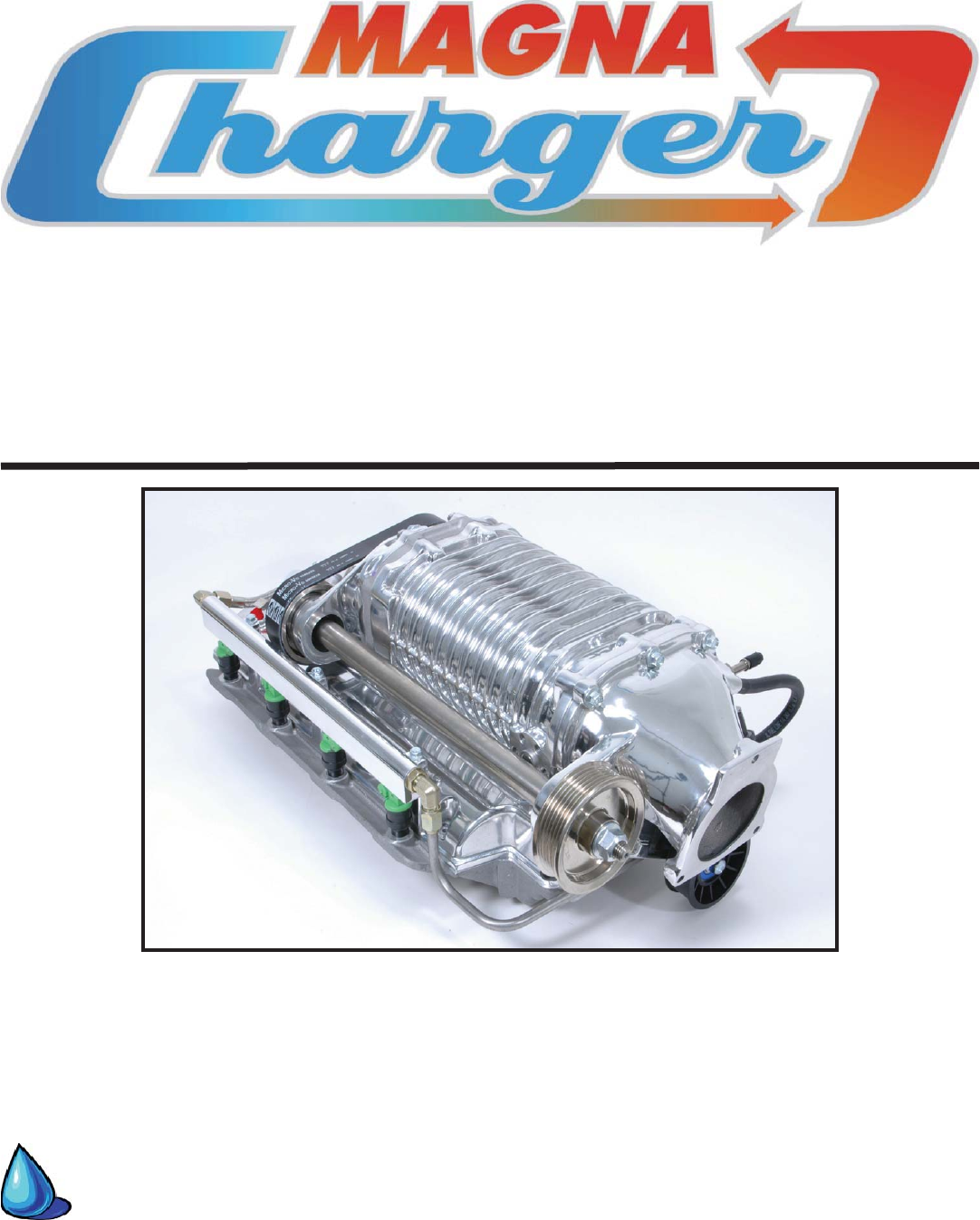
SUPERCHARGER INSTALLATION MANUALMagna ChargerGM 6.0 Liter Engine2005-2007 C6 Corvette LS2Please take a few moments to review this manual thoroughly be
66. Using compressed air, blow the drill shavings out of the holes. 67. Install the supplied reamer into drill. Using a small amount of oil, ream h
69. Use compressed air to blow out the holes. 70. Insert the two supplied hardened roll pins into the drilled holes. The use of a small hammer and
73. With the crankshaft modifi cations complete, replace the power steering line previously re-moved and tighten the fi tting securely.74. Replace the
77. Torque the sub-frame, sway bar connections and motor mounts to the torque values below:Torque Specifi cations:Engine sub-frame nuts 80 ft-lbsMo
81. Remove the brake cooling duct, it will pull out.82. Unbolt the horn assembly with a 13mm wrench83. Squeeze the electrical connector on the horn
85. This is the intercooler coolant pump and its mounting clamp. Note: The plastic caps on the inlet and out should be removed before the hose conne
89. Start the Heat exchanger installation by ap-plying the adhesive backed foam strip to the back side of the heat exchanger top and bottom tanks. Th
93. Install the heat exchanger by sliding it in front of the radiator. The heat exchanger will sit on the fl at area immediately in front of radiator
97. Using the 1” hole saw again, create one or two holes in the right hand splash panel below the radiator. This is where the coolant lines will pas
101. Connect one end of the remaining length of hose to the pump outlet an loop it over the top of the pump. Continue the hose out through the new h
Tools RequiredMetric wrench set1/4” - 3/8” and 1/2” drive metric socket set (standard & deep)3/8” and 1/2” drive Foot pound and inch pound torque
105. Remove the stock tensioner assembly by removing the two mounting bolts with a 15mm wrench.106. Install the new tensioner assembly in place of t
109. Install the new vent pipe with the original bolts and torque them with a torque wrench and 10mm socket to 106 in-lbs110. Remove the electrical
113. The gasket will be reused, the original valley cover will not. Inspect the gasket for any damage and then re-install, note that it will only fi
117. Remove the upper radiator hose from the water pump housing by squeezing the spring clamp and pulling the hose free.118. Using a power steering
121. Remove the small hose from the bottom of the reservoir and set it aside for re-mounting in a later step.122. Using the length of 5/8” hose supp
125. Re-install the mounting bolts back into the alternator bracket and tighten to 50 Nm (37 ft-lbs).126. Remove the wiring harness anchor from the
129. Slide the PS reservoir into place on the new mounting bracket.130. Route the 5/8” PS hose along the fan shroud, following the same path as the
133. Route the new hose from the small barb on the PS reservoir along the same path as the 5/8” hose and trim it to length. Connect the hose se-cure
137. Connect the hose from “T” fi tting to the barb on the coolant vent pipe. Secure the hose with the #4 clamp provided.138. Remove the throttle bo
141. Install the throttle body onto the inlet mani-fold using the original bolts. Tighten the bolts with a 10mm socket and torque wrench to 106 In-L
Stock ClipStock ClipHood BoltsHood Bolts1. Raise the vehicle on a automotive hoist using the factory recommended lift points. Refer to the owners ma
145. Install the two intake manifold gaskets sup-plied onto the recesses in the manifold face.146. Install the fuel manifold O-ring into the recess
150. Carefully, set the supercharger assembly on the engine, line up the bolt holes with the holes in the cylinder heads. (Be careful of the one bol
153. Install the new supplied supercharger and accessory fan belt with a 15mm tensioner wrench, using the new supplied belt routing dia-gram below.15
157. Remove the air fi lter boxes from the air tube assembly by loosening the retaining clamps with a straight blade screw driver.Retaining clampsReta
162. Install the new air fi lter elements and re-clip the hoods onto the fi lter boxes.163. Here is a dismantled view of the new inlet assembly. Note
165. Slide the air boxes into the gaskets on the lower air tube and secure them there using the original clamps.166. Install a gasket onto the Mass
169. Assemble the upper air tube assembly onto the lower and install themon the vehicle as shown.170. With the air tube and fi lter assemblies in pla
173. Locate the original EVAP line that con-nected the solenoid to the inlet manifold. Using a shop knife, cut the plastic tubing where it meets the
177. Connect the remaining end of the new EVAP line to the barb on the driver side of the inlet manifold.178. Connect the original EVAP hard-line to
181. Assemble the PCV outlet hose by cutting a 2” length and attaching one end to the 90 degree “Elbow” fi tting. Attach the other end to the barb on
6. Remove the six push-lock fasteners securing the rear splash panel.5. Remove the front right wheel with a 17mm wrench. 7. Remove the Push-lock f
185. Insert the new brake vacuum check valve into the end of the 11/32” vacuum hose supplied.186. Install the check valve and hose assembly into the
189. Open the Fuse/Relay center cover. Re-move the positive (B+) battery cable connections by removing the securing nut with a 12mm socket wrench.
193. Locate the GREY wire in the A7 location, cut the wire approximately 1-1/2” from the block and strip the insulation back 1/4” from both ends. Lo
197. Route the black wires with the ring con-nectors from both the Magnavolt harness and the intercooler relay down to the ground terminal located di
202. Using the hose supplied, connect one end of the hose to the pressure port and then route the other end to the Magnavolt module. Secure the hose
205. Install the eight Injector Wiring Adaptors on to the harness fuel injectors connectors. 206. Install the eight Injector adaptors on to the fuel
209. Install the ETC connector onto the throttle body.210. Locate the Manifold (ETC) connector and peel back the tape and split-loom to expose the w
213. Locate the MAF sensor connector and peel back the tape and split loom to expose the wires. Approximately 3” from the connector cut all the wire
218. Re-install the computer on the mounting bracket using the original fastener and a 10mm socket wrench. Note: If your vehicle has a auto-matic tr
221. Fill the radiator reservoir with a 50:50 mix-ture of purifi ed water and GM approved engine coolant only. After the initial start up and the en-
9. Removing the inner fender panel will expose the vehicles operating computer.10. There are three computer connectors, Grey, Black, and Blue. Remo
After the initial test drive gradually work the vehicle to wide open throttle runs, listen for any engine detonation (pinging). If engine detona-tion
13. Here are the shipping materials supplied to quickly return the vehicle computers to Magnuson Products Inc.14. Place the computers into the plast
17. Remove the engine oil fi ller cap, then remove the engine/coil covers by pulling up fi rmly on them. The covers will not be reused.18. Replace th
21. Remove the air fi lter cover by pulling out on the ends and lifting the cover free. 22. Remove the air fi lter hood clips on both air fi lter elem
© 2020, manymanuals.de. Alle Rechte vorbehalten. | 0.430 s |
 Manymanuals.com
 Manymanuals.de
 Manymanuals.fr
 Manymanuals.it
 Manymanuals.pl
 Manymanuals.cz
 Manymanuals.es
 Manymanuals-pt.com
Kommentare zu diesen Handbüchern