Chevrolet 2004 Corvette Bedienerhandbuch Seite 26
- Seite / 40
- Inhaltsverzeichnis
- LESEZEICHEN
- CHEVROLET 1
- CORVETTE 1
- FOREWORD 2
- TABLE OF CONTENTS 3
- IMPORTANT NOTES 4
- CHEVROLET CORVETTE 5
- PARTS LIST 10
- 1. PREPARATION/REMOVAL 13
- Fig. 2-b 14
- Fig. 2-a 14
- Fig. 2-c 15
- Fig. 3-a 15
- Fig. 3-c 16
- Fig. 3-b 16
- Fig. 4-a 16
- 5. SURGE TANK RELOCATION 17
- Transmissions Only) 18
- 7. ALTERNATOR RELOCATION 18
- Fig. 7-c 19
- Fig. 7-b 19
- Fig. 7-d 19
- Fig. 7-e 19
- Fig. 7-f 20
- Fig. 7-g 20
- Fig. 8-a 21
- Fig. 8-c 21
- Fig. 8-b 21
- Fig. 8-d 22
- Fig. 8-e 22
- Fig. 8-f 22
- 9. ABS MODULE RELOCATION 23
- Fig. 10-a 24
- Fig. 10-b 24
- Fig. 11-a 24
- Fig. 11-b 25
- Fig. 11-c 25
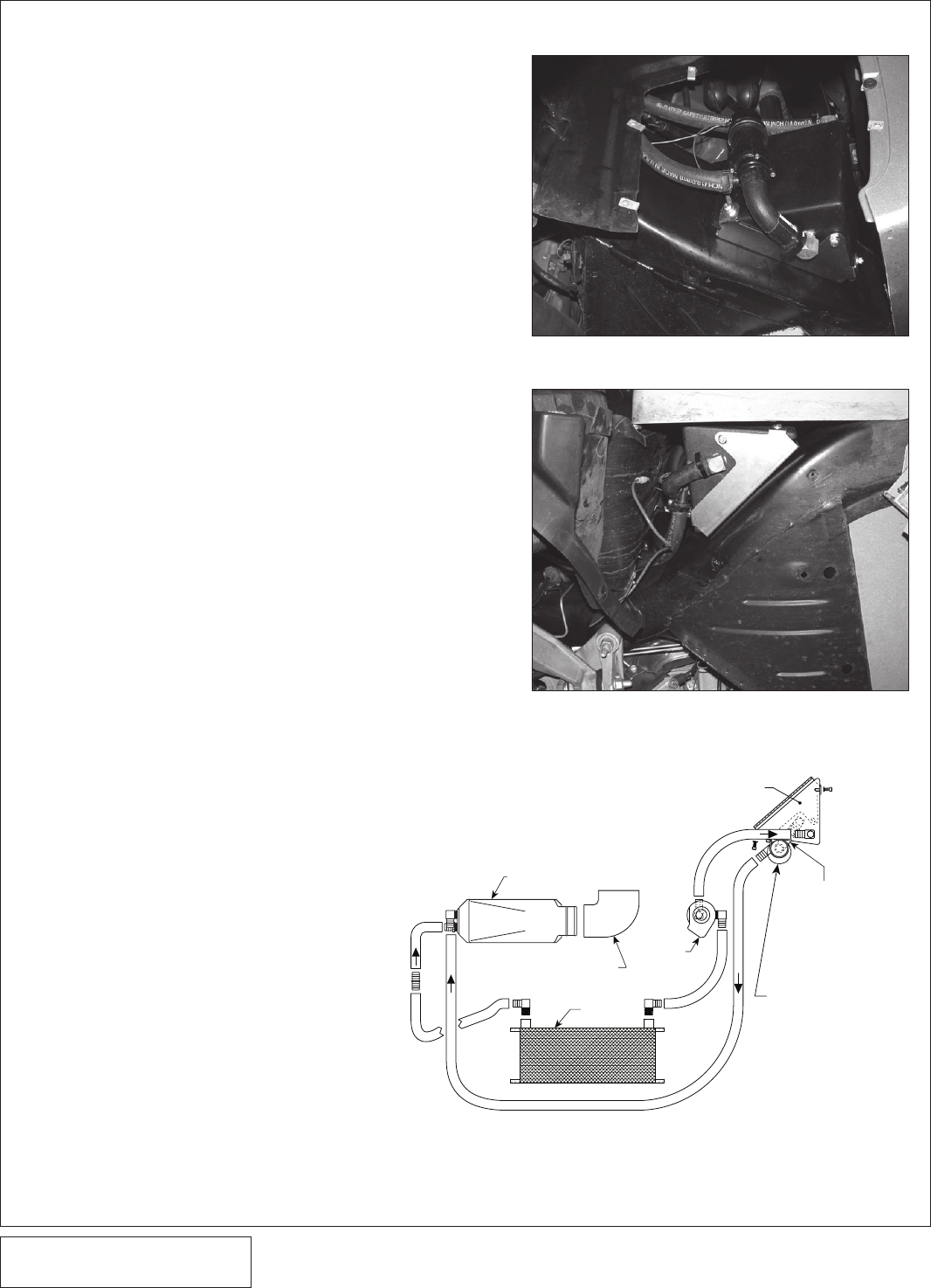
- Fig. 13-a 26
- Fig. 13-b 26
- Fig. 13-c 26
- Fig. 13-e 27
- Fig. 13-d 27
- Fig. 13-f 27
- Fig. 13-g 27
- Fig. 13-i 28
- Fig. 13-j 28
- Fig. 13-h 28
- Fig. 13-l 29
- Fig. 13-k 29
- Fig. 13-m 29
- Fig. 13-n 29
- Fig. 14-a 30
- Fig. 14-c 30
- Fig. 14-b 30
- Fig. 14-d 31
- 16. INLET DUCT INSTALLATION 33
- Fig. 17-a 34
- 18. REFLASH COMPUTER 35
- Fig. 18-d 36
- Fig. 18-e 36
- YOUR VEHICLE! 37
- 19. FINAL ASSEMBLY AND CHECK 38
- ENGINEERING, LLC 40
© 2020, manymanuals.de. Alle Rechte vorbehalten. | 1.596 s |
 Manymanuals.com
 Manymanuals.de
 Manymanuals.fr
 Manymanuals.it
 Manymanuals.pl
 Manymanuals.cz
 Manymanuals.es
 Manymanuals-pt.com
Kommentare zu diesen Handbüchern